Structure and Feature of Screw Press
Description will be made on the friction screw press by the most fundamental friction driven system, however, the only difference is the driving method and there exists no difference of performance after the flywheel rotation except servo driven mechanism. (The servo driven mechanism is able to reduce speed by a motor during the slide is descending and stops at the start position by the motor before one cycle of process completes.)
1 Structure and Feature
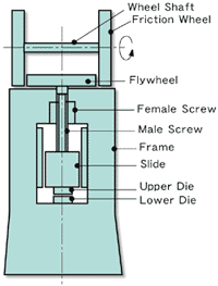
Generally, the machine has female screw fixed to crown part of the frame and male screw is combined with it. On the upper part of the male screw, very high capacity flywheel is firmly tightened. At the lowest part, the slide is linked to something like bearings. This is the typical manual screw press and if the flywheel rotates CW, the slide descends while the flywheel does CCW, the slide ascends. The slide descends until upper tool interferes with lower tool. If there are no tools, the flywheel clashes against the upper part of the frame crown while the slide ascends until lower part of the frame crown collides. The structure is completely common for various screw presses that have no mechanical lower-dead-point and upper-dead-point. This is very important issue to know the possibility of serious accident such as machine breakage come from miss-operation. At both side of the flywheel, two friction wheels are supported with shaft and bearings and are always rotating in one direction through motor. The friction wheels during this moment condense large revolution energy. The flywheel is wound with leather clutch lining and normally, if LH friction disc contacts the flywheel, it rotates CW, while RH friction disc makes it rotate CCW. In the same manner, if the flywheel rotates CW and CCW, the slide also ascends and descends through screw mechanism.

Basic Friction Driven Type
2 Explanation on One Press Cycle Operation
The one cycle process is done as: The slide and the flywheel are at upper limit. LH friction disc contacts the flywheel as START switch depressed. The flywheel contacted the friction disc inner part where peripheral velocity is slow starts to rotate CW and moves toward outer part where the peripheral velocity is high with acceleration through screw mechanism. Flywheel revolution speed reaches maximum right before stamping at around slide stroke end. The maximum flywheel energy gives the material momentary and impulsive stamping pressure. All the flywheel energy is consumed at this moment and the flywheel stops in an instant. Just after this, operation is changed by electrical signal to contact the right hand side friction disc with the flywheel and the flywheel rotates reversely for the slide goes up. Brake works at the preset upper limit position and the machine terminates one cycle operation.
3 Machine Structure
-
A.Frame
Straight side type is commonly used because the frame needs to absorb all large flywheel energy through screw mechanism. In small and medium size machines, monolithic frame is used and in large machine, two to four divided frames are fastened with tie-rod. The machine has big difference from other machines that receives large inertia moment toward flywheel rotation direction during stamping and that generates torsion stress.
-
B.Slide
Different from other press machines, the slide receives torsion toward the screw rotation direction and it is rotated toward the same direction during stamping. That is why long slide type with equal or more than four-point guide is popular.
-
C.Male Screw
The screw is also called as lead screw or spindle screw, too. Since it receives impulsive torsion and compression stresses, heat treated chrome molybdenum steel or nickel chrome molybdenum steel is used. Since screw angle is generally desined more than 15 degrees not to be self-made locking, the screw becomes multiple thread screw of two to four threads of trapezoidal or square threads as a matter of convenience of thread valley cutting process. The screw angle is being desined smaller for self-made locking required device, such as a vice.
-
D.Female Screw
The screw is also called as guide screw or spindle nut, too. It requires durability in weariness and toughness. High strength brass or aluminum bronze casting is used. It is mounted into the frame as the structure has a male screw moved vertically while in the others, into the slide (In double-screw type, both are used)
-
E.Flywheel and Clutch Belt
The clutch belt is furnished with flywheel's circumference in the friction driven type. Linear contact is made and that requires characteristic of flexibility and durability against heat. Currently, natural leather product is commonly used. In some rare cases, asbestos-free lining is used in the clutch part, but hazardous nature of broken piece splash around exists, so the use of it should be avoided unless surrounding is completely covered. Though slipping device (torque limiter) is used to discharge excess energy from overload sometimes, it becomes obsolete because more reliable approach that uses electronic signal from strain gauge furnished with the frame to stop becomes popular.
-
F.Friction Disc
It is also called as friction wheel, too. Basically, it is a primary flywheel that stores revolution energy all the time. It has three roles; storing energy, heat radiation generated from friction transmission and clutch function in operation. This wheel does not exist in a direct drive system, such as servomotor driven type.
-
G.Wheel Shaft
Since large machine needs heavy friction wheel and large clutch cylinder capacity because two wheels move horizontally at the same time. And large inertia creates impact force as lining contacts the wheels. Thus the type that moves left and right independently is commonly used. In mid and small machines, the type that the shaft and two wheels are fixed and moves together is well used
-
H.Brake
Disc brake or shoe brake against flywheel circumference is popular. The brake that is completely different from other mechanical press machines is that it needs to have large capability to stop the flywheel completely in very short time every press cycle operation.
The motor itself has a role of brake to break speed and stop in servomotor driven method but a mechanical brake is also equipped for emergency use when power failure. -
I.Lever&Handling Mechanism
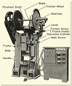
The mechanism that for operator usage to move the wheel shaft horizontally so as to do the slide vertically. Rarely used except for specific application in small machine.
-
J.Operation Cylinder
The cylinder that drives the wheel shaft horizontally. Pneumatic cylinder is used rather than hydraulic one. The machine with the lever has one cylinder in the middle of the lever while the others without the lever have two cylinders at the both end of the shaft.
-
K.Slide Balancing Device
It balances the slide weight as well as eliminating screw's backlashes generated after long time usage.

Parts and Name of Screw Press


